Using an HC-SR04 sonar with the BeagleBone
Now that RoboGames 2013 has come and gone, I've been browsing the internet for some new and interesting components to use in robotics projects. One sensor that has recently come to my attention is the HC-SR04 sonar. It functions exactly the same as existing dual-transducer piezoelectric sonars such as the SRF05 and the Ping))), but there is one notable difference - the price.
A 4-pack of Ping))) sonars is $100 and the SRF05 usually runs about $19 depending on the current GBP/USD exchange rate. When buying in single-digit quantities directly from China, the HC-SR04 approaches $1.50 per unit - an order of magnitude reduction in cost.
I was a bit skeptical if such a cheap device could have the same performance as the sonars we've been using for the past decade, so I ordered a 20-pack from eBay. ePacket shipping took over a month, but for the price of a single Ping))) sonar I now have 20 of them. Somewhat to my surprise, my testing shows that they perform similarly to the Ping))).
Beaglebot
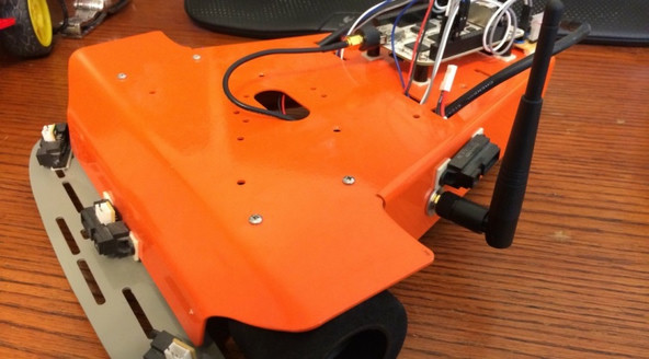
Beaglebot is a small differential drive robot built on a Robotics Connection Stinger chassis. It uses a BeagleBone, a 720 MHz ARM SBC that is geared towards robotics and industrial control. Unlike boards such as the new Raspberry Pi, it integrates a substantial number of peripherals you might otherwise expect to find in a microcontroller, not a Linux capable computer - things such as GPIO pins, PWM controllers, quadrature encoder drivers, and analog inputs. My goal for Beaglebot is to only use the functionality present in the BeagleBone without needing to include an Arduino or other microcontroller in its design.
Driving the Sonar
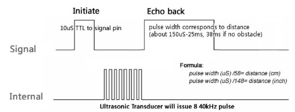
Most of these basic sonars operate on the same principle - a trigger signal is sent to the sonar, which then sends out a rapid series of ultrasonic clicks at a precise frequency and asserts its echo output. When the clicks bounce off an object and return to the sonar, the receiving transducer begins to oscillate. Only a narrow band of frequencies (typically centered around 40 KHz for hobby sonars) will make the piezoelectric transducer "ring". The sonar will then deassert the echo output. The duration of this pulse corresponds to the distance the obstacle was at. You can then divide the duration by two to get the one-way flight time and then multiply by the speed of sound.
This works out to dividing the pulse duration in microseconds by 148 to get the distance in inches.
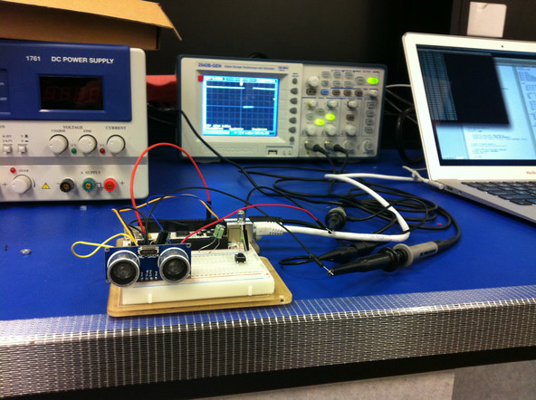
Hardware Interface
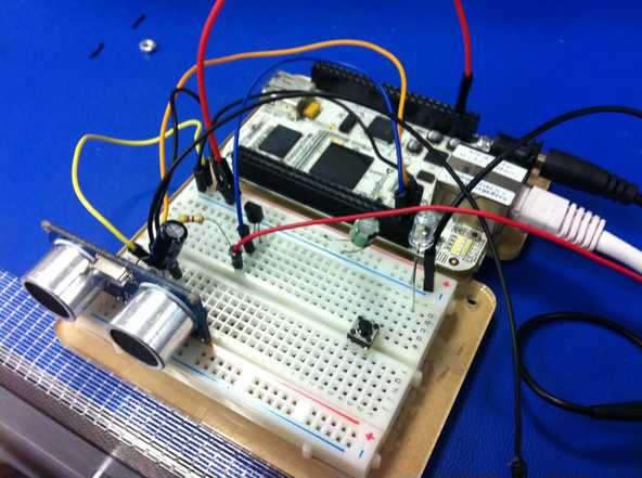
The HC-SR04 is a 5 volt device, but the maximum safe voltage on the GPIO pins of the BeagleBone is 3.6 volts, so we need to add some logic to level-shift the output from the sonar. Since the BeagleBone's GPIOs have programmable pull-up resistors, all we need to do is connect an NPN transistor between a GPIO pin and ground, and the base to the output of the sonar. The trigger pin can be directly connected to another GPIO pin.
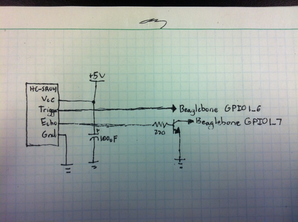
The rest of this post assumes the trigger is connected to GPIO1_6 and the echo transistor is connected to GPIO1_7.
Attempt 1 - Linux Kernel Module
My previous approach to writing sonar code on the Arduino was to use interrupts to handle the falling edge of the echo signal. I'd store the current time when I triggered the sonar, and then sample the time again on the interrupt. The difference between the two was the duration of the pulse. I figured I could take the same approach with the BeagleBone.
I'd never implemented a kernel module before so I wasn't particularly familiar with how interrupts work on Linux. It ended up being fairly simple to put together a small kernel module that would run some code upon a GPIO pin change. However, the results were very poor. I was getting extremely jittery or maybe even random measurements.
What I didn't realize is that interrupt latency on Linux can be rather long, at least from the perspective of realtime events. The real interrupt queues a handler that will run your code at a later time. As a consumer of GPIO interrupts, I don't have much control over their latency. This makes them entirely useless this application. Jitter of even a single millisecond will throw off the measurement by nearly a foot.
Clearly I needed to take a different approach.
Attempt 2 - AM335x PRU Subsystem
In addition to the high performance Cortex-A8 "application" core, the AM335x SoC in the BeagleBone has two high speed microcontroller cores called PRUs (Programmable Realtime Units). These share the system bus with the main CPU - meaning that they can access all of the memory, the IO devices, etc. They also both have a dedicated interrupt to the CPU so that they can signal when they’ve completed some action.
I wrote a simple program in PRU assembly that pulses the trigger pin on the sonar and counts the time until the echo. It writes the result to the PRU's local scratchpad memory, which is accessible to the main processor. The PRU then triggers an interrupt so the processor knows to read the result. This has resulted in substantially higher accuracy.
The guide on how to use the sample code is here on GitHub.